Please help me and give me your opinion and share your knowledge about sump construction.
Others i have talked to, who ownes the same tank thinks it is a design flaw, but Red Sea have not been helpfull when they got intouch with them.
This is a tank that comes with a rear sump, but you can upgrade to a in-cabinet sump by bying Red Seas sump upgrade kit, which i have done.
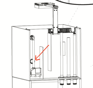
The tank has already holes for pipping with plugs in them. When you upgrade to the in-cabinet sump, you just remove the 3 plugs and install the plumping and you put in a open flow grill (the picture with the red arrow) instead of the old closed one.
So, the problem is getting the waterlevel to stay the same in the in-cabinet sumps returnpump chamber and in the overflow (the old rear sump).
No matter what i do, the water will slowly rise in the overflow, eventually causing the water to go down the emergency pipe.
Because of this, the return pump chamber cant keep the same waterlevel either, making it impossible to install my ATO.
Red Sea reccomend to get a returnpump with a flow of at least 2700 lph. I bought the Sicce Syncra SDC 6.0 which has a minimum flow rate of 2000 and a maximum flow rate 5500 (lph), and i can adjust the flow with a controller.
I have, of course, adjustet the pump MANY times, but with the same outcome.
My question:
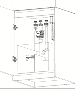
So, the "old returnpump" (the pump that was used when the sump was working as a rear sump, is still in the setup. And the chamber where it is located is in direct watercontact with the chamber where the pipes are (the main downpipe and the emergency pipe), as you can see on the picture from the manual.
In the "old returnpump" chamber is also a open flowgrill, as i mentioned above, (the red arrow on the picture), so this chamber gets water from the display tank, which means the overflow (old rear sump) and display tank is connected.
The people i have talked to, who also deals with this problem, thinks that this is a design flaw because the evaporation from the entire surface will affect the water level in the overflow. Instead of a small overflow having insignificant evaporation, you have evaporation from the entire display tank affecting the waterlevels, because the overflow and the display tank are connected.
Can you please tell me, will i ever be able to solve this problem, as long as the overflow and display tank are connected?
Or is it me who are doing something wrong?
Others i have talked to, who ownes the same tank thinks it is a design flaw, but Red Sea have not been helpfull when they got intouch with them.
This is a tank that comes with a rear sump, but you can upgrade to a in-cabinet sump by bying Red Seas sump upgrade kit, which i have done.
The tank has already holes for pipping with plugs in them. When you upgrade to the in-cabinet sump, you just remove the 3 plugs and install the plumping and you put in a open flow grill (the picture with the red arrow) instead of the old closed one.
So, the problem is getting the waterlevel to stay the same in the in-cabinet sumps returnpump chamber and in the overflow (the old rear sump).
No matter what i do, the water will slowly rise in the overflow, eventually causing the water to go down the emergency pipe.
Because of this, the return pump chamber cant keep the same waterlevel either, making it impossible to install my ATO.
Red Sea reccomend to get a returnpump with a flow of at least 2700 lph. I bought the Sicce Syncra SDC 6.0 which has a minimum flow rate of 2000 and a maximum flow rate 5500 (lph), and i can adjust the flow with a controller.
I have, of course, adjustet the pump MANY times, but with the same outcome.
My question:
So, the "old returnpump" (the pump that was used when the sump was working as a rear sump, is still in the setup. And the chamber where it is located is in direct watercontact with the chamber where the pipes are (the main downpipe and the emergency pipe), as you can see on the picture from the manual.
In the "old returnpump" chamber is also a open flowgrill, as i mentioned above, (the red arrow on the picture), so this chamber gets water from the display tank, which means the overflow (old rear sump) and display tank is connected.
The people i have talked to, who also deals with this problem, thinks that this is a design flaw because the evaporation from the entire surface will affect the water level in the overflow. Instead of a small overflow having insignificant evaporation, you have evaporation from the entire display tank affecting the waterlevels, because the overflow and the display tank are connected.
Can you please tell me, will i ever be able to solve this problem, as long as the overflow and display tank are connected?
Or is it me who are doing something wrong?